
Are you selecting flanges for an industrial piping system but unsure whether to use weld neck, slip-on, or blind flanges? Choosing the correct flange type is important for connecting pipelines, installing industrial equipment, managing maintenance access, and maintaining pressure-boundary integrity.
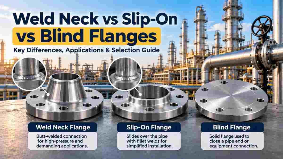
The main difference between weld neck, slip-on, and blind flanges is their design and function. A weld neck flange connects to a pipe through a butt weld, a slip-on flange fits over a pipe and is typically secured using fillet welds, and a blind flange closes a flanged pipe opening without allowing flow through it.
These flange types are commonly used in oil and gas facilities, chemical processing plants, power generation systems, water treatment facilities, and other industrial installations.
Shubham Metals supplies industrial flanges in different material grades, sizes, and configurations.
This guide explains weld neck vs slip-on vs blind flanges, including their construction, industrial applications, installation considerations, pressure classes, inspection requirements, and purchasing specifications.
Weld neck flanges are designed for butt-welded pipe connections, slip-on flanges use a pipe-overlap arrangement with fillet welds, and blind flanges provide a bolted closure for a pipe or equipment opening.
Each type serves a different purpose in an industrial piping system.
The key differences include:
Weld Neck Flange: Features a tapered hub and is joined to the pipe using a butt weld.
Slip-On Flange: Slides over the pipe and is normally attached through welds at the flange hub and pipe end.
Blind Flange: Contains no central flow opening and is bolted to a compatible mating flange to close a pipeline or equipment connection.
Weld neck and slip-on flanges connect piping components, while blind flanges are primarily used for closure.
The appropriate selection depends on operating pressure, temperature, loading conditions, service requirements, inspection needs, and the applicable engineering code.
Explore the Alloy Steel Flanges Collection to review available industrial flange configurations.
A weld neck flange is a pipe flange with a tapered hub that is connected to the pipe through a butt weld. Its design provides a gradual transition between the pipe and flange, making it suitable for many demanding industrial piping applications.
The weld neck flange has a neck that extends from the flange body toward the connected pipe.
During installation, the flange is aligned with the pipe, and the joint is welded using an approved welding procedure.
Weld neck flanges are commonly selected when the piping system requires a welded connection with favorable stress distribution and suitable inspection access.
Potential benefits include:
A tapered hub that provides a gradual structural transition.
Suitability for demanding pressure and temperature conditions when properly rated.
Compatibility with many industrial piping systems.
The ability to perform applicable volumetric examination of the butt weld.
Use in systems subject to significant mechanical or thermal loading.
Their actual performance depends on the flange material, design, weld quality, operating conditions, and applicable code.
Weld neck flanges are commonly used in refineries, petrochemical facilities, power plants, and other engineered piping systems where a butt-welded connection is appropriate.
Applications may include:
Industrial process piping.
High-temperature steam lines.
Oil and gas processing facilities.
Chemical manufacturing plants.
Power generation systems.
Certain pressure equipment connections.
Weld neck flanges should be specified according to the actual service conditions rather than automatically selected for every industrial application.
A slip-on flange is a flange that fits over the outside diameter of a pipe and is typically secured using fillet welds on the outside and inside. Its geometry can simplify initial alignment during installation.
The pipe is inserted through the flange opening and positioned according to the approved fabrication procedure.
The flange is then attached using the specified weld configuration.
Slip-on flanges offer a straightforward assembly arrangement and can be suitable for piping systems where their design, welding requirements, and service limitations are acceptable.
Potential advantages include:
Relatively straightforward pipe positioning.
Convenient alignment during initial assembly.
Common availability in industrial flange product ranges.
Suitability for certain utility and process piping systems.
Potentially lower initial component and fabrication costs in some applications.
However, fabrication cost depends on the required welds, inspection, material, and installation conditions.
Slip-on flanges are not automatically appropriate for every pressure, temperature, or cyclic service.
Slip-on flanges are commonly used in industrial piping systems where the applicable engineering code and service conditions permit fillet-welded flange connections.
Possible applications include:
Water distribution piping.
Certain utility systems.
Industrial process lines.
Cooling water networks.
Selected low- and moderate-duty piping services.
The final choice should consider design pressure, temperature, corrosion, cyclic loading, and relevant restrictions in the piping code.
A blind flange is a solid flange without a central bore that is bolted to a compatible mating flange to close a pipe end, valve connection, vessel nozzle, or other flanged opening.
Unlike weld neck and slip-on flanges, a blind flange does not normally provide a through-flow connection.
It is designed to form a closure within the specified pressure-temperature limits of the complete assembly.
Blind flanges provide a removable bolted closure that can support maintenance, future expansion, and pressure-boundary closure when correctly designed and installed.
Common benefits include:
Closing unused flanged pipe connections.
Allowing future piping extensions.
Providing access for certain maintenance activities.
Closing equipment nozzles.
Supporting appropriate pressure-testing arrangements.
Blind flanges require compatible gaskets, bolting, facing, and pressure-temperature ratings.
They should not be confused with all forms of positive isolation used in industrial maintenance procedures.
Blind flanges are used at pipeline ends, unused equipment connections, pressure vessel nozzles, and designated maintenance or testing points.
Typical applications include:
Pipeline termination points.
Unused process connections.
Equipment nozzles.
Future pipeline expansion locations.
Certain pressure-testing arrangements.
Maintenance access points.
A blind flange must be suitable for the specified design pressure, temperature, material, and flange connection.
Weld neck flanges are frequently preferred for demanding pressure, temperature, or cyclic loading conditions because of their butt-welded construction and tapered hub. However, suitability must be verified against the applicable design code and project requirements.
A higher-pressure piping system may require careful evaluation of connection geometry, weld design, fatigue performance, and inspection requirements.
When comparing weld neck and slip-on flanges, consider:
Design pressure.
Operating temperature.
Material allowable stress.
Mechanical loading.
Vibration and fatigue.
Welding procedure requirements.
Inspection requirements.
Applicable piping code restrictions.
A flange's pressure class alone does not establish the suitability of every connection type for a particular service.
The selection should be approved through the project's engineering process.
Yes. Blind flanges can be used in high-pressure piping systems when their material, dimensions, pressure class, facing, gasket, and bolting are suitable for the specified operating conditions.
Blind flanges experience pressure loading across the closed opening.
Their design and allowable service conditions must therefore be evaluated carefully.
Important considerations include:
Applicable flange standard.
Material grade.
Pressure-temperature rating.
Nominal pipe size.
Flange thickness and geometry.
Gasket design.
Bolting specification.
Installation and assembly requirements.
An incorrectly specified blind flange can create serious pressure-boundary risks.
Weld neck flanges generally require a butt weld, while slip-on flanges are typically installed using fillet welds at specified locations. These different joint configurations affect fabrication, inspection, and applicable code requirements.
Weld neck flanges are normally joined to the pipe through a full-penetration butt weld using an approved welding procedure.
The welding process should consider:
Base material.
Pipe wall thickness.
Joint preparation.
Welding procedure qualification.
Welder qualification.
Preheat requirements.
Post-weld heat treatment where required.
Appropriate examination methods.
The specified weld quality requirements depend on the governing construction code and service conditions.
Slip-on flanges are generally secured through fillet welds on the inside and outside of the flange connection, as required by the applicable installation specification.
During fabrication, verify:
Correct pipe insertion depth.
Appropriate flange positioning.
Required weld dimensions.
Suitable welding materials.
Approved welding procedures.
Applicable inspection requirements.
Correct flange alignment.
Improper pipe positioning or inadequate welds can affect connection performance.
A conventional blind flange normally does not require welding to the pipe because it is installed as a bolted closure against a mating flange.
The assembly typically includes:
Blind flange.
Compatible mating flange.
Appropriate gasket.
Specified bolts and nuts.
Approved assembly procedure.
Certain special designs may differ, so the project specification should control the installation method.
ASME B16.5 provides requirements for pipe flanges and flanged fittings, including pressure-temperature ratings, dimensions, materials, tolerances, marking, and other relevant specifications.
The standard covers applicable flange sizes and pressure classes within its defined scope.
Common pressure classes include:
Class 150.
Class 300.
Class 400.
Class 600.
Class 900.
Class 1500.
Class 2500.
Not every class is available for every size or configuration.
The exact scope must be checked in the applicable edition.
An ASME flange pressure class is a standardized rating designation used with the applicable material group and operating temperature to determine allowable pressure-temperature ratings.
A Class 300 flange does not simply mean that the flange is always rated for 300 psi.
Actual ratings depend on the material and temperature.
Engineers must use the appropriate rating tables and governing piping design code.
ASME B16.5 covers pipe flanges and flanged fittings within its specified smaller nominal size range, while ASME B16.47 addresses large-diameter steel flanges.
ASME B16.5 primarily covers NPS 1/2 through NPS 24, subject to the standard's applicable rating and product provisions.
ASME B16.47 covers NPS 26 through NPS 60 and includes Series A and Series B dimensional arrangements.
Buyers should specify the applicable standard before ordering, particularly for large-diameter flanges.
Raised face, flat face, and ring type joint describe different flange facing arrangements that influence gasket selection and joint assembly. The facing must match the connection design and applicable standard.
A raised face flange has a raised gasket-contact surface around the bore and is commonly used in industrial piping systems.
The facing is designed to work with suitable gasket arrangements and compatible mating components.
A flat face flange has a gasket-contact surface extending across the flange face without a raised sealing area.
Flat face connections may be specified for particular equipment and piping arrangements.
A ring type joint flange uses a machined groove designed for a compatible metallic ring gasket.
These connections are used in selected services requiring a specifically engineered flange and gasket arrangement.
Do not substitute one facing for another without confirming compatibility and obtaining engineering approval.
Flange material selection for high-temperature service depends on allowable stress, temperature limits, corrosion conditions, welding requirements, and the governing equipment or piping code.
Alloy steel flange grades are commonly considered for certain high-temperature applications.
For example, ASTM A182 includes forged alloy and stainless steel flange materials, with grade-specific requirements.
When selecting materials, consider:
Maximum design temperature.
Design pressure.
Required mechanical properties.
Material specification.
Thermal expansion.
Corrosion or oxidation conditions.
Welding requirements.
Heat treatment.
Relevant testing.
Shubham Metals supplies Alloy Steel Flanges in several grades for industrial purchasing requirements.
The exact material grade and pressure-temperature limits must be verified for the project.
Carbon steel flanges are commonly selected for suitable general industrial services, while alloy steel flanges incorporate specified alloying elements to meet particular mechanical, temperature, or environmental requirements.
Their suitability depends on grade and service conditions.
Carbon steel flanges may be used in:
General process piping.
Utility systems.
Water and industrial service lines.
Certain oil and gas applications.
Alloy steel flanges may be selected for:
Elevated-temperature piping.
Certain high-pressure systems.
Power generation equipment.
Specialized industrial applications.
Buyers can explore Carbon Steel Flanges and Alloy Steel Flanges through Shubham Metals.
Slip-on flanges may offer convenient initial positioning, but installation complexity depends on the required welds, accessibility, inspection procedures, and service requirements.
Weld neck flanges require appropriate butt-weld preparation and alignment.
Slip-on flanges typically require correctly positioned fillet welds.
Blind flanges use a bolted closure arrangement that requires proper gasket selection and controlled assembly.
Installation planning should account for:
Site access.
Pipe alignment.
Welding time.
Weld examination.
Gasket installation.
Bolting procedures.
Required post-weld treatment.
Safety precautions.
A flange should not be selected solely because it appears easier to install.
The most cost-effective flange depends on the application, material grade, manufacturing requirements, installation work, inspection, and long-term maintenance needs.
Slip-on flanges may offer lower initial component costs in some sizes and materials, but the total installed cost depends on fabrication and inspection.
Weld neck flanges may involve greater initial fabrication requirements while offering advantages in appropriate demanding services.
Blind flanges serve a different purpose and should be evaluated as closure components rather than direct substitutes for connecting flanges.
Compare:
Flange purchase price.
Material grade.
Pressure class.
Welding requirements.
Inspection costs.
Installation labor.
Gasket and bolting costs.
Maintenance accessibility.
Project downtime.
Long-term reliability requirements.
Engineering suitability must come before price comparison.
Engineers should select industrial flanges for oil and gas applications based on design pressure, operating temperature, fluid properties, material compatibility, mechanical loading, and applicable industry requirements.
A structured process includes:
Identify the applicable piping or equipment code.
Determine design pressure and temperature.
Select an appropriate flange material.
Establish the required pressure class.
Choose the flange type.
Confirm facing and gasket compatibility.
Review pipe dimensions and wall thickness.
Define welding and examination requirements.
Specify bolting and assembly procedures.
Verify applicable documentation and testing.
Additional requirements may apply for sour service, cyclic loading, corrosive environments, or specialized equipment.
The final design should be reviewed by qualified engineering personnel.
Before purchasing industrial flanges, buyers should confirm the flange type, nominal size, pressure class, material grade, dimensional standard, facing, and documentation requirements.
Use this procurement checklist:
Flange type: Weld neck, slip-on, blind, or another specified configuration.
Nominal size: NPS or DN.
Pressure class: Applicable ASME class or other rating.
Material grade: Required ASTM, ASME, or equivalent specification.
Dimensional standard: ASME B16.5, ASME B16.47, or another applicable standard.
Flange facing: RF, FF, RTJ, or another specified design.
Bore: Required bore dimensions where applicable.
Pipe schedule: Applicable to the matching pipe connection.
Testing: Required inspection and examination.
Documentation: Material test certificates and traceability requirements.
Quantity: Number of flanges.
Delivery: Packaging and destination.
For weld neck flanges, buyers should pay particular attention to bore dimensions and matching pipe wall thickness.
For slip-on flanges, confirm fit-up dimensions and welding requirements.
For blind flanges, verify the closure design and matching connection details.
Industrial flange quality checks should include visual inspection, dimensional verification, material identification, surface-condition checks, marking verification, and required testing documentation.
Important checks include:
Flange outside diameter.
Bolt-hole dimensions and positions.
Flange thickness.
Facing condition.
Hub and bore dimensions, where applicable.
Surface damage.
Material grade identification.
Heat-number traceability.
Required test reports.
Compliance with purchase specifications.
Examine machined gasket-contact surfaces for damage that could affect sealing.
Project-specific nondestructive examination may also be required.
Inspection acceptance criteria should follow the applicable material and dimensional specifications.
Common flange selection mistakes include choosing the wrong connection type, confusing pressure class with actual allowable pressure, overlooking facing compatibility, and failing to match flange dimensions to the piping system.
Avoid:
Selecting flange type solely by purchase price.
Assuming all flanges of the same class have identical service suitability.
Mixing incompatible flange facings.
Ignoring operating temperature.
Specifying the wrong material grade.
Omitting matching pipe dimensions.
Overlooking welding requirements.
Failing to verify bolt and gasket compatibility.
Ignoring material traceability.
Using an incorrect dimensional standard.
Accurate flange specifications can reduce procurement delays and installation problems.
Shubham Metals supplies industrial flanges in several material categories, including alloy steel, carbon steel, and duplex steel, for engineering and procurement requirements.
Based in Bangalore, India, the company serves customers requiring industrial metal products.
Its website lists flange configurations including:
Weld neck flanges.
Slip-on flanges.
Blind flanges.
Threaded flanges.
Socket weld flanges.
Lap joint flanges.
Product categories include:
Buyers should confirm current sizes, grades, pressure classes, inventory, and required documentation when requesting a quotation.
The most common questions concern pressure suitability, welding methods, sealing arrangements, maintenance applications, and the differences between flange types.
A weld neck flange may be more appropriate for certain demanding pressure, temperature, or cyclic loading conditions. A slip-on flange may suit other services where its connection design is permitted. Selection depends on engineering requirements.
Slip-on flanges may be permitted in certain pressurized systems, but their suitability depends on the applicable code, pressure-temperature ratings, welding design, and service restrictions.
No. A conventional blind flange does not have a central flow bore. It is designed to close a compatible flanged opening.
Yes. Appropriately rated blind flanges may be used in certain pressure-testing arrangements. The complete test setup must be designed and reviewed for the applicable test pressure and safety requirements.
Weld neck flanges are generally connected through a full-penetration butt weld, subject to the approved joint design and welding specification.
Slip-on flanges typically use internal and external fillet welds. The exact requirements depend on the applicable fabrication code and approved installation details.
Yes. Conventional blind flanges are bolted closures and can be removed after the system has been properly isolated, depressurized, drained, and made safe according to approved procedures.
Class 150 is a standardized pressure-class designation. It does not mean the flange always has a maximum working pressure of 150 psi. The allowable rating depends on material and operating temperature.
They may use compatible gasket designs when their nominal size, pressure class, facing, and other connection requirements match. Gasket suitability must be verified for the complete joint.
A blind flange is commonly used to close an unused flanged connection that may be opened for future piping expansion. The connection must remain properly designed, rated, and maintained.
You can request industrial flanges from Shubham Metals by sharing the required flange type, nominal size, pressure class, material grade, dimensional standard, facing, quantity, and delivery requirements.
For an accurate quotation, provide:
Flange type.
Nominal size.
Material specification and grade.
Pressure class.
Dimensional standard.
Flange facing.
Matching pipe dimensions, where applicable.
Required inspection or testing.
Material certification requirements.
Quantity.
Delivery location.
A complete technical enquiry helps the supplier identify the requested products and clarify availability.
Looking for an industrial flange supplier in India?
Explore Alloy Steel Flanges, Carbon Steel Flanges, and Duplex Steel Flanges from Shubham Metals to review available product categories and request pricing.
Technical Note: Flange selection, pressure-temperature ratings, welding, and bolted-joint assembly are engineering decisions. Final specifications should be verified by qualified professionals using the applicable standards, codes, and project requirements.